
The decision in brief
For a conventional passive electric guitar, cable capacitance can change the loaded pickup response. Compare capacitance per unit length together with the length connected before the first active buffer. A lower per-metre figure does not guarantee lower total capacitance or a sound you prefer. Confirm the correct instrument connection, then compare the actual cables in your normal rig.
Read the connection before the capacitance figure
This guide concerns a shielded instrument lead between a conventional guitar output and a supported instrument input. Confirm those endpoints first. A shared quarter-inch plug does not make a speaker cable suitable for that job. Our speaker and instrument cable comparison covers that separate decision.
Capacitance describes electrical charge storage between the cable’s conductors. Specifications often give it per metre or per foot. pF means picofarads, a unit of capacitance; 1,000 pF equals 1 nF. Keep the unit with the number. A value for a whole lead and a value per metre answer different questions.
In the passive-pickup circuit BOSS describes, cable capacitance affects the high-frequency response and resonance. The pickup, controls and receiving input also belong to that circuit. Cable data alone cannot establish a universal frequency response, an audible difference or a preferred sound.
Sources: BOSS: passive pickups, cable loading and buffer placement
Multiply the specified value by the required length
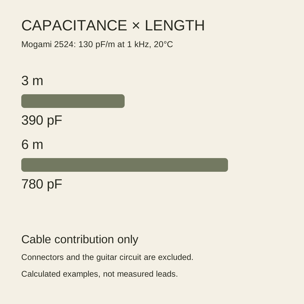
Mogami lists its 2524 cable at 130 pF/m, measured at 1 kHz and 20°C. Use that documented value for a simple example: cable contribution ≈ capacitance per metre × length in metres. The lengths here are proposed runs, not assembled products we measured.
| Example at 130 pF/m | Calculation | Cable contribution |
|---|---|---|
| 3 m run | 130 × 3 | 390 pF (0.39 nF) |
| 6 m run | 130 × 6 | 780 pF (0.78 nF) |
Doubling the length doubles this calculated contribution. It does not prove that one lead sounds twice as dark or loses a fixed amount of treble. Those conclusions would require the complete circuit and suitable measurements or listening evidence.
For different cable types in one uninterrupted passive path, estimate each contribution separately and add them. For example, the same specification table gives 2319 as 155 pF/m. A proposed 3 m run of 2524 plus 1 m of 2319 contributes approximately 390 + 155 = 545 pF. Connections, switching and the guitar’s own wiring are outside that cable-only estimate. A 3 m run at 155 pF/m contributes approximately 465 pF, less than the 780 pF of a 6 m run at 130 pF/m. The lower per-metre value does not settle that comparison.
Sources: Mogami: 2319 and 2524 cable capacitance at 1 kHz and 20°C
Mark where the passive path reaches a buffer
Draw the route from the guitar to the first active buffer or other powered stage that presents the intended input and a low-impedance output. Include patch leads and bypassed pedals that leave the passive signal passing through. Check each device’s manual: its bypass behavior and power state determine the route.
A buffer changes the source driving the next cable segment. The cable before it still loads the pickup; moving a buffer later cannot remove that earlier contribution. Cables after it remain part of the rig, but should not all be treated as one unbuffered pickup load.
BOSS explains the impedance change and the consequences of long passive paths. Its article promotes buffered pedals, so treat the mechanism separately from a purchase recommendation. This guide does not adopt its length examples as universal hearing limits. Input-sensitive fuzz, wah and other devices may need a particular placement; use their instructions before changing the chain.
The pedal-order guide helps record the processing route. For wireless equipment, inspect any cable-tone simulation separately from latency; they are different specifications.
Sources: BOSS: passive pickups, cable loading and buffer placement
Make a comparison that preserves the playing conditions
- Use two identified, suitable instrument leads. Record each cable type, length and published capacitance if available.
- Keep the same guitar, pickup selection, guitar controls, amplifier settings and first-buffer position. Note whether pedals are active or bypassed.
- Mute the listening path before changing instrument connections, then restore the same manageable listening level.
- Play the same short clean phrase, including the attack and decay of higher notes. Then repeat through the gain settings you actually use.
- Write what you heard and which condition you preferred. If you change gain, EQ or guitar volume, record that as an additional change.
This is a proposed observation routine, not a blind trial or a result we obtained. A longer cable of a different design changes more than one variable. If you cannot identify a useful repeatable difference, that session provides no reason to pay for an assumed tonal improvement.
Keep intermittent faults separate from tonal loading
A crackle, dropout or loose plug needs a connection check. It is not a capacitance reading. With the listening path muted, substitute one known suitable lead, restore the level and repeat the same movement. Record whether the symptom follows the lead or stays with a socket. Do not pull on the connector or continue bending a damaged jacket.
| Record | Why it helps |
|---|---|
| Exact lead and length | Identifies the cable-only comparison |
| Guitar controls and first buffer | Defines the loading context |
| Passage and rig settings | Makes the next comparison repeatable |
| Tonal preference or fault symptom | Keeps two different questions separate |
Inspect the jacket and strain relief without dismantling the lead. A damaged cable can be replaced or assessed by a competent repairer. A published capacitance figure does not verify a particular plug, solder joint or cable’s present condition.
Choose a practical run and keep the useful result
Start with enough length for your actual movement and secure routing. Compare the total cable contribution in that route, then decide whether a different lead or a documented buffer arrangement changes something you need. Lower capacitance is a circuit option, not a quality score.
For an active pickup or onboard-preamp output, verify that system’s output and connection requirements. The passive-pickup example may not predict the same degree of loading. Do not infer an active output from a pickup cover or the presence of a battery elsewhere in the instrument.
Retain the settings and observation record that led to your choice. If you later change the pickup system, pedal bypass modes or first active stage, revisit the route before attributing the new sound to the cable alone. The next useful check is the complete pickup and signal system, rather than another unsupported cable ranking.
How this guide was prepared
We checked Mogami’s official 2319/2524 specification table and BOSS’s explanation of passive-pickup loading and buffers on October 26, 2026. The 3 m and 6 m examples are editorial calculations from one published cable value, not measurements of finished leads. Diagrams simplify the connection and omit component parasitics. We performed no cable, capacitance or listening test and claim no human specialist review. Manufacturer explanations do not establish a universal audible threshold.
Documentation checked .